Sensors and Encoders
Overview
This document provides information and guides for using the various angle sensor and encoder types supported by Tinymovr.
Connector Overview
R5.3

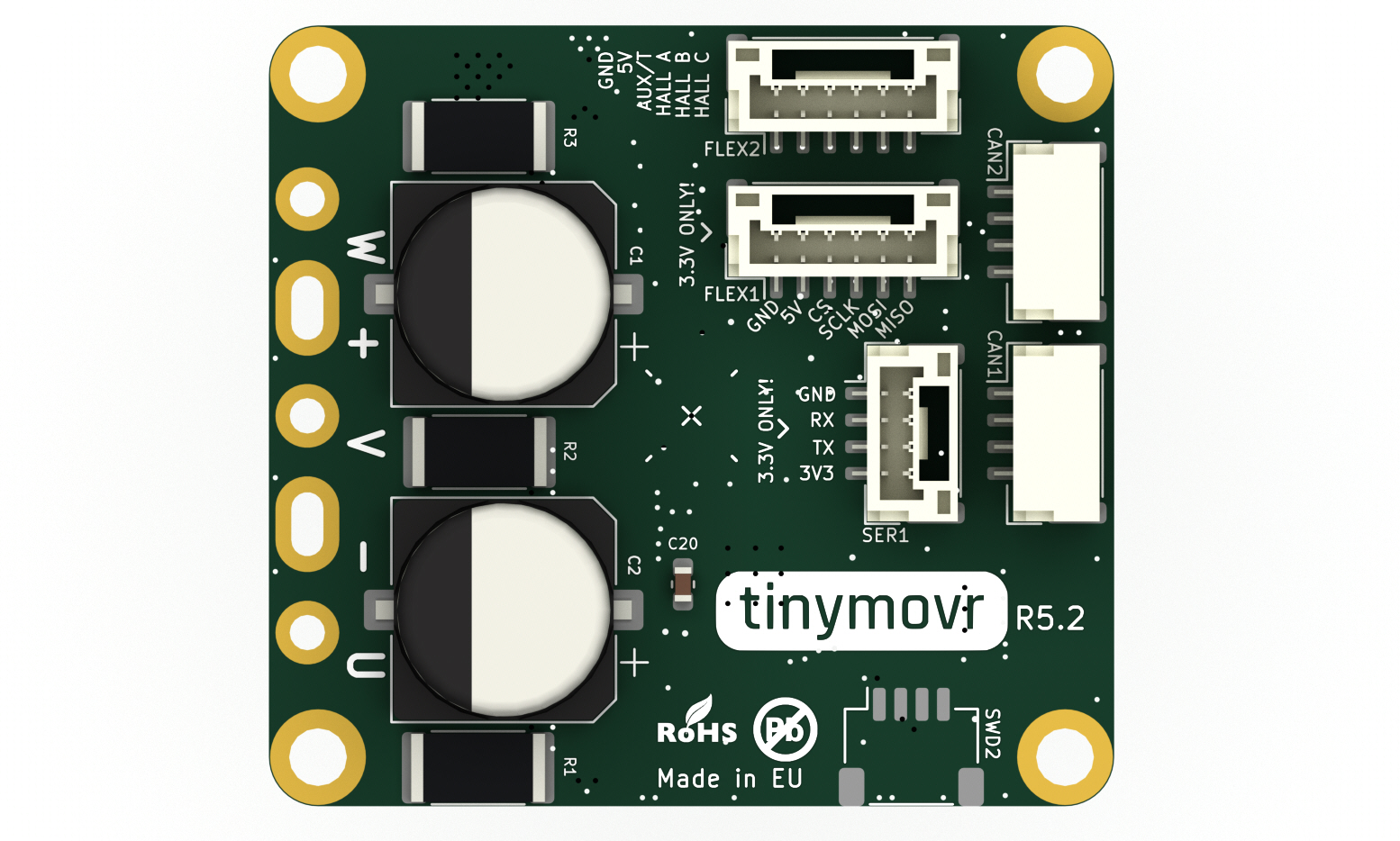
R5.2
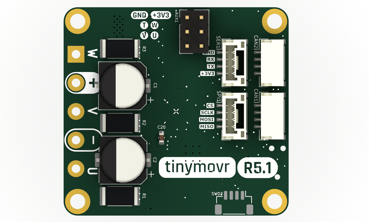
R5.1
M5.1/M5.2

Hardware Setup
External SPI Sensors
Tinymovr supports a number of external sensors over the SPI bus. Currently, the MPS MA7xx, the AMS AS5047 and the CUI AMT22 sensors are supported.
Note
Even though Tinymovr R5.2 has the FLEX2 port which can function as SPI, due to a hardware incompatibility this port does not implement SPI correctly. As such, external sensors are only supported on the M5.x series at the moment.
Tinymovr R5.3 and above does not have this issue and supports external SPI sensors normally.
MPS MA7XX
The MPS MA7XX are compact absolute angle magnetic sensors. We offer a breakout that is compatible with Tinymovr M5.x, but you can also use the MPS supplied evaluation board.

A total of six wires need to be connected: 5V, GND, MISO, MOSI, SCLK and CS.
AMS AS5047
The AMS AS5047 is a compact absolute angle magnetic sensor. It is compatible with Tinymovr M5.x. In the connection diagram below, we consider the AS5047 breakout board issued by AMS.
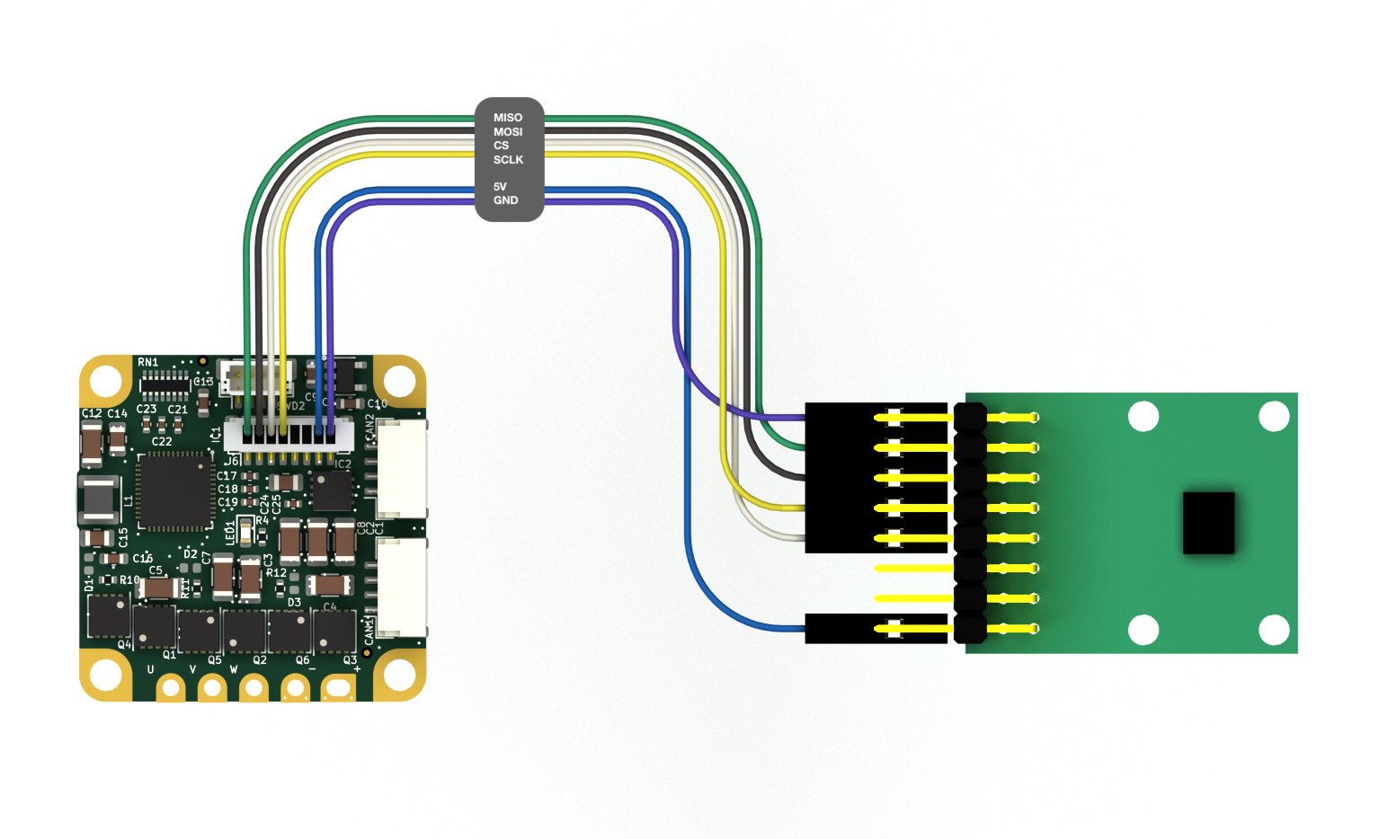
A total of six wires need to be connected: 5V, GND, MISO, MOSI, SCLK and CS.
CUI AMT22
The CUI AMT22 is an absolute angle, 12 or 14-bit capacitive sensor. It is compatible with Tinymovr M5.x.
A total of six wires need to be connected: 5V, GND, MISO, MOSI, SCLK and CS If using the AMS AMT-06C-1-036 prototype cable, you can additionally connect the cable shield (black wire) to one GND pin on the CAN bus ports or the SWD port.
Hall Effect Sensor
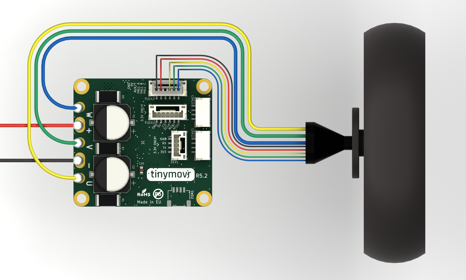
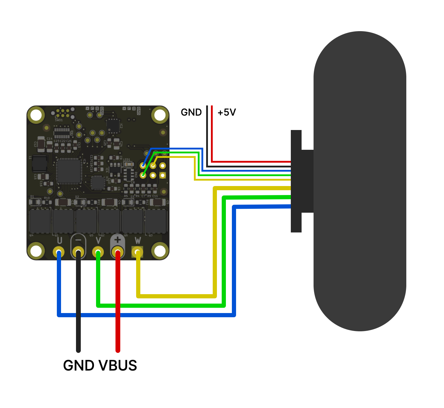
To use Hall effect sensors, you need to connect the sensor’s power supply, phases and ground to the correct pins on the FLEX1 header of the Tinymovr R5.2 or greater, or the AUX header of the Tinymovr R5.1. Note the U, V and W pins. These need to be connected to the respective pins of the sensor. The pin labeled AUX/T is an input for a thermistor, but is currently not in use. In addition, power supply and GND pins need to be connected to the sensor.
Note
Tinymovr R5.2 and above supply 5V on the FLEX1 power supply pin. You can safely connect this to the Hall effect sensor + terminal.
Tinymovr R5.1 supplies 3.3V on the AUX power supply pin. If your sensor uses 5V, or if it needs more than 50mA, you’ll need to provide power externally, e.g. through a dedicated buck converter.
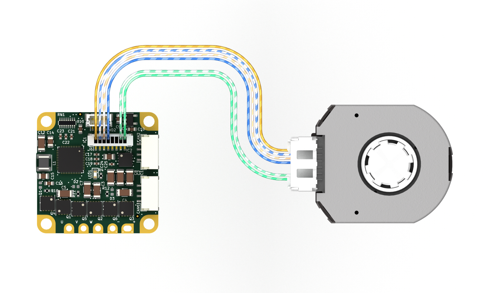
Example
The figures below shows an example of wiring a hubwheel motor to Tinymovr R5.2 and R5.1 respectively, using the embedded Hall effect sensors of the motor for commutation.
Units
In Tinymovr, a ‘tick’ traditionally represents 1/8192 of a full mechanical rotation. The system utilizes floating-point values, thereby allowing resolution beyond the granularity of a single tick — down to the precision defined by the IEEE754 standard. This means that even when high-resolution sensors (with 16, 18, 20 or more bits) are employed, their precision is fully retained. Internally, sensor measurements are scaled to conform with the 8192-tick representation. In addition, using the Tinymovr client library, you can define commands in any angle unit you with, such as turns, rads, degrees etc. This gives you freedom in your application beyond the tick representation.
Reference Frames
In the context of Tinymovr motor control, reference frames are essential for understanding the transformation of sensor data and user setpoints into motor control signals. The following diagram depicts the reference frames and their interconnections:
The diagram below illustrates the flow of data from the physical sensors through various observers and frames, finally reaching the motor.
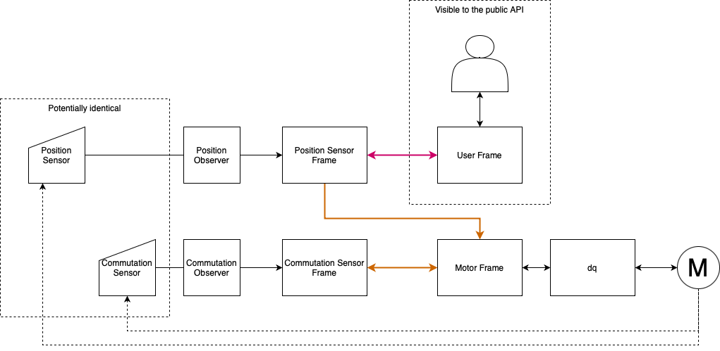
Position Sensor Frame (PSF)
The Position Sensor Frame (PSF) corresponds to the filtered position sensor data. The main function of this frame is to provide feedback on the estimated position and velocity of the rotor, and therefore provide feedback to the position and velocity control loops. As the homing and trajectory planners also rely on position and velocity estimates, this frame also affects those functions.
Commutation Sensor Frame (CSF)
The Commutation Sensor Frame (CSF) corresponds to the filtered commutation sensor data. In ths simplest scenario, the position and commutation sensors are the same, as such the PSF and CSF are identical. The main function of this frame is to provide the estimated rotor angle to the current control loop, so that the electrical angle is derived in the Motor Frame, for Field Oriented Control.
Note
The transform between MF and CSF always has a scale factor of 1. In other words, the commutation sensor is always assumed to be mechanically attached directly to the motor shaft, without reduction.
Motor Frame (MF)
The origin of the Motor Frame (MF) corresponds to the zero electrical angle of the electrical cycle energized during calibration. This is the frame used by current control, and related dq, inverse Park and SVPWM transforms.
User Frame (UF)
The User Frame is the interface exposed to the Tinymovr API, allowing the user to command the motor using position, veocity and current setpoints. This frame is related to the PSF, so that the user commands are predominantly based on the position data, with the commutation aspect being internally managed by the firmware’s observer algorithms.
Frame Transforms
Data from the Position and Commutation Sensors is forwarded to their respective observers. The observers are responsible for filtering the sensor readings and providing position and velocity estimates. This processed data is then translated into two separate frames:
The Position Sensor Frame, which carries the filtered position data.
The Commutation Sensor Frame, which ensures the motor’s proper electrical commutation.
These frames are then employed to inform the Motor Frame, which is the final reference before actuating the motor.
As a summary, the following ransforms are derived during calibration and are stored in the Tinymovr firmware:
UF <-> PSF
PSF <-> CSF
CSF <-> MF
UF <-> MF
Tinymovr makes use of the XF1 library, which has been developed for this purpose and offers convenience functions to perform transforms, derive transforms from data, as well as inverse and constrained transforms.
Sensor Configuration
The sensor configuration consists of two steps. The first step concerns the setup of the individual sensors being used, and the second step concerns sensor selection. The corresponding sections in the device spec are tm1.sensors.setup, and tm1.sensors.select.
Sensor Setup
Onboard Magnetic Sensor
Tinymovr R and M series feature an onboard magnetic absolute angle sensor that allows high precision angle measurement for efficient commutation and highly dynamic motor control. This is enabled by default and does not require any specific setup, apart from initial reference frame calibration.
The Onboard Magnetic Sensor does not require any configuration. In this section the calibration state and any sensor errors can be seen.
External SPI Sensor
The External SPI Sensor requires the correct sensor type to be set before enabling it. Three sensors are currently supported, the MPS MA7xx series, the AMS AS504x series, and the CUI AMT22 series. In addition, here you can see the calibration state and sensor errors.
Hall Effect Sensor
Hall effect sensors generate a specific sequence in the 3 phase Hall effect sensor signal as the rotor moves. By reading this sequence, the rotor position is determined in one of six 60 degree sectors along the electrical cycle.
The Hall Effect Sensor does not require any configuration. In this section the calibration state and any sensor errors can be seen.
Sensor Selection
Sensor selection can be performed for positioning and for commutation. In both cases, the selection should be performed after hardware setup and any sensor setup has been fully completed, namely if using external sensors, the selection of the sensor type. The selection is among ONBOARD, EXTERNAL_SPI and HALL sensors. Once selection is complete, the Tinymovr needs to undergo calibration.
Examples
External AS5047 Sensor for Commutation and Positioning
Note
This is only supported on the Tinymovr M series, and upcoming Tinymovr R versions
Ensure the hardware is properly connected.
Then, configure the external sensor type as follows:
tm1.sensors.setup.external_spi.type = tm1.sensors.setup.external_spi.type.AS5047
Then select the EXTERNAL_SPI sensor for each of the position and commutation sensors:
tm1.sensors.select.commutation_sensor.connection = tm1.sensors.select.commutation_sensor.connection.EXTERNAL_SPI
tm1.sensors.select.position_sensor.connection = tm1.sensors.select.position_sensor.connection.EXTERNAL_SPI
At this point, you are ready to perform motor/sensor calibration. This will measure the R and L values of the motor, derive frame transforms and eccentricity compensation tables.
tm1.controller.calibrate()
After calibration finishes, you should be able to control the motor:
tm1.controller.velocity_mode()
tm1.controller.velocity.setpoint = 8192 # 60 rpm
The motor should now move at a constant velocity.
Once you have determined that the motor behaves as expected, set to idle and perform another config save to persist the configuration:
tm1.controller.idle()
tm1.save_config()
External AMT22 Sensor for Positioning and Onboard MA702/704 for Commutation
Note
This is only supported on the Tinymovr M series, and upcoming Tinymovr R versions
Ensure the hardware is properly connected.
Then, configure the external sensor type as follows:
tm1.sensors.setup.external_spi.type = tm1.sensors.setup.external_spi.type.AMT22
Then select the EXTERNAL_SPI sensor for each of the position and commutation sensors:
tm1.sensors.select.commutation_sensor.connection = tm1.sensors.select.commutation_sensor.connection.ONBOARD
tm1.sensors.select.position_sensor.connection = tm1.sensors.select.position_sensor.connection.EXTERNAL_SPI
At this point, you are ready to perform motor/sensor calibration. This will measure the R and L values of the motor, derive frame transforms and eccentricity compensation tables.
tm1.controller.calibrate()
After calibration finishes, you should be able to control the motor:
tm1.controller.velocity_mode()
tm1.controller.velocity.setpoint = 8192 # 60 rpm
The motor should now move at a constant velocity.
Once you have determined that the motor behaves as expected, set to idle and perform another config save to persist the configuration:
tm1.controller.idle()
tm1.save_config()
Hall Effect Sensor
Note
This is only supported on the Tinymovr R series.
Ensure the hardware is properly connected.
Then select the HALL sensor for each of the position and commutation sensors, and configure the observer bandwidth as follows:
tm1.sensors.select.commutation_sensor.connection = HALL
tm1.sensors.select.position_sensor.connection = HALL
tm1.sensors.select.commutation_sensor.bandwidth = 200
tm1.sensors.select.position_sensor.bandwidth = 20
This sets the type to Hall effect sensor, and each of the commutation and position observer bandwidths. The commutation observer is set to a higher bandwidth value, in order to ensure that commutation is accurate and a runoff scenario is avoided.
Next, you need to set the motor pole pairs:
tm1.motor.pole_pairs = 15
Next comes tuning of gains. Gains are determined on the tick count of a full mechanical turn of the motor. When using the an absolute sensor, the tick count is fixed to 8192 ticks (the resolution can be higher as the tick count is a floating point value).
When using the Hall effect sensor, the tick count is defined as 8192 ticks in an electrical cycle. Thus, your mechanical cycle tick count is variable, depending on the pole pair count of your motor. Because of this it is possible that the gains need to be updated. Below we present an example of values that work well with a 15 pp hoverboard motor:
tm1.controller.position.p_gain = 5
tm1.controller.velocity.p_gain = 0.00001
For your own motor, you need to determine these experimentally. Take a look at PID Tuning for more information.
At this point, you are ready to perform motor/sensor calibration. This will measure the R and L values of the motor, as well as the hall effect sensor sequence.
tm1.controller.calibrate()
After calibration finishes, you should be able to control the motor. Note that the default reference frame for the hall sensors maps to 8192 ticks per motor electrical cycle. You can change this by modifying the user frame multiplier:
tm1.sensors.user_frame.multiplier = 1
Go ahead and enter velocity control mode, and set a setpoint:
tm1.controller.velocity_mode()
tm1.controller.velocity.setpoint = 80000 # around 60 rpm for a 15 pp motor
The motor should now move at a constant velocity.
Once you have determined that the motor behaves as expected, set to idle and perform another config save to persist the configuration:
tm1.controller.idle()
tm1.save_config()
Observer Bandwidth
Tinymovr uses a second order observer that filters readings from the sensors, and maintains a position and velocity state. The bandwidth value corresponds to the desired observer bandwidth. It is a configurable value and depends on the dynamics that you wish to achieve with your motor. Keep in mind that high bandwidth values used with motors with fewer pole pairs will make the motors oscillate around the setpoint and have a rough tracking performance (perceivable “knocks” when the rotor moves). On the other hand, too low of a bandwidth value may cause the motor to lose tracking in highly dynamic motions. If you are certain such motions will not be possible (e.g. in heavy moving platforms) you may reduce the bandwidth to ensure smoother motion.