Hardware Setup
Requirements
A 3-phase brushless motor (see below for supported types)
A means to talk CAN Bus, such as CANine or a Canable-compatible adapter.
A mechanical rig that ensures firm connection between the Tinymovr PCB and the brushless motor. Designs that can be 3D printed are available.
Note that the Tinymovr Servo Kit includes all of the above in a ready to use kit.
Supported Motor Types
Most three-phase pancake-style outrunners can be used with Tinymovr. While there is a lot of variation between motors of even the same size and external appearance, as a general rule-of-thumb motors ranging from 40mm outer diameter to 110mm should work fine with Tinymovr.
(image)
Mechanical Setup
Mounting motor and Tinymovr
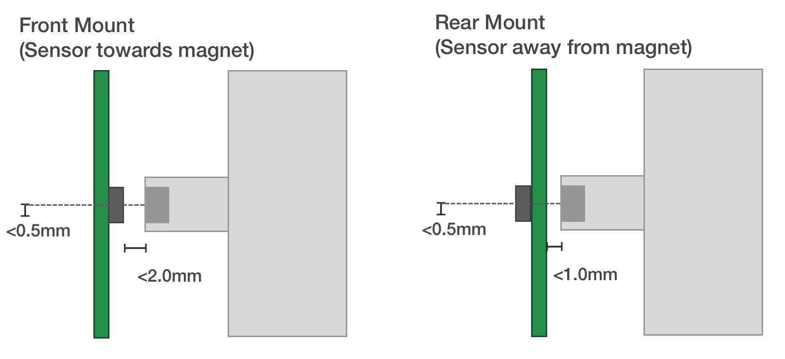
The most important aspect of a correct setup is to ensure the controller is properly positioned in relation to the motor. The center of the PCB, where the encoder is located, should lie as close to the motor rotation axis as possible. In addition, the distance from the encoder magnet to the encoder IC should be less than 2mm (less than 1mm if you are mounting the PCB packwards, i.e. the encoder IC is facing away from the magnet).
Tinymovr and motor mechanical mounting
A 3D printable encoder magnet jig is available, suitable for 6mm disc magnets and 14, 19, 25 and 30mm motor hole diameters.
For a 3D printable motor mount design, check out the Tinymovr alpha dev kit mount (suitable for 40xx motors).
Note
For safety reasons, you should always ensure the motor & controller assembly are secured to a stable surface before operation. The motor rotor may experience high acceleration that may cause damage or injury if not secured properly.
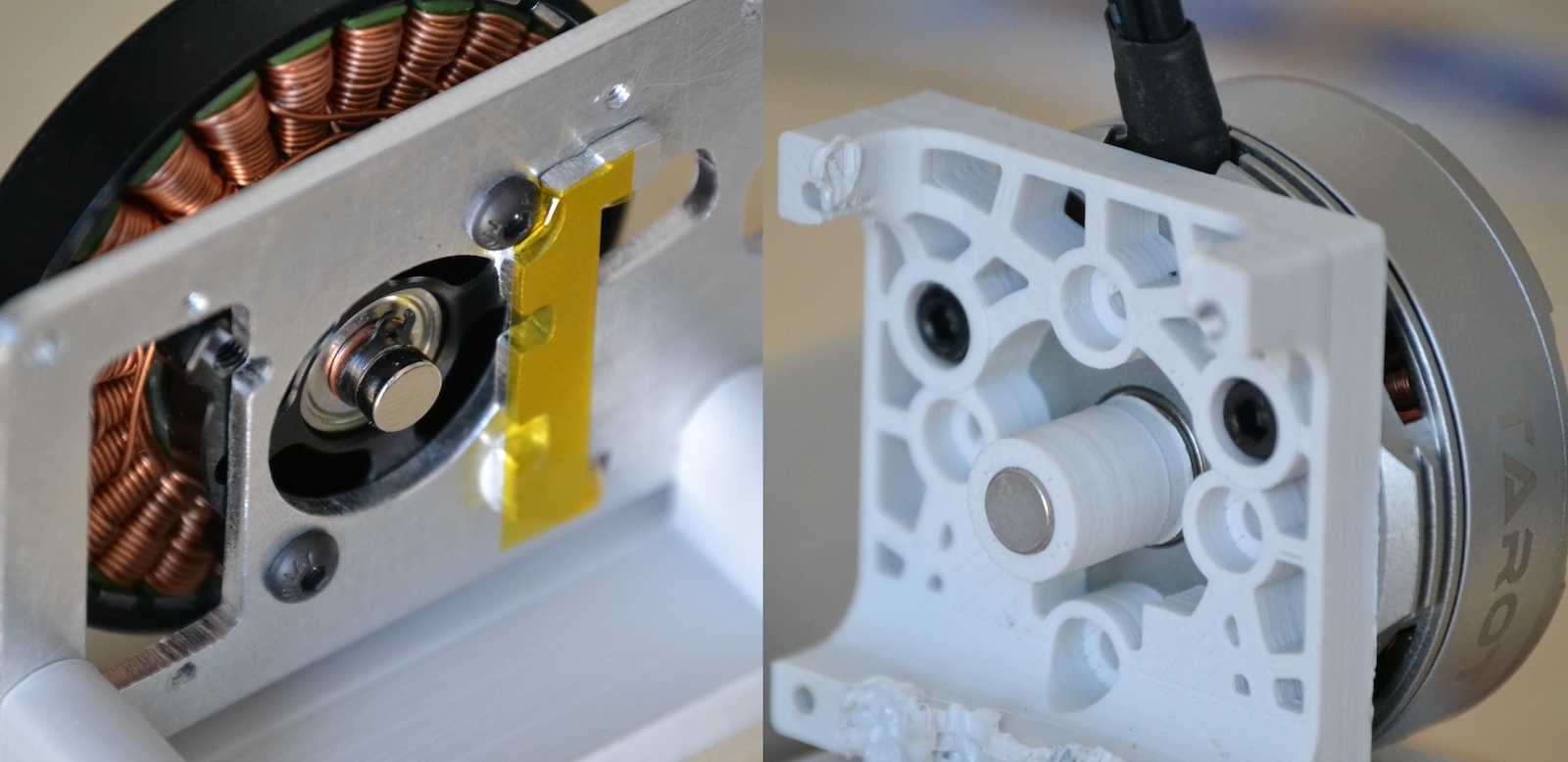
Left: Magnet mount directly on shaft. Right: Magnet mount using 3d-printed holder.
Magnet on the rear side of the PCB
TL;DR: It is possible to have the magnet on the rear dise of the PCB, i.e. opposite of the magnet sensor IC, but the gap needs to be reduced to account for the PCB thickness.
This has been verified by MPS in this forum post, quoted below:
[…] this type of arrangement is possible, what really matters in the end is that there is enough magnetic field reaching the sensor. Of course the minimum distance is imposed by the thickness of the PCB, so it puts some constraints on the design, that you have to take into account when chosing the magnet (you can use our online simulation tool for that). But as long as the PCB is not acting as a magnetic shield (due to copper plane), then it is fine.
Mounting Tips
Ensure the encoder magnet is firmly attached to the motor shaft, otherwise it may slip out of sync. Use strong adhesive to secure.
Calibration needs to be performed without any loads on the motor. If the motor is coupled to a load, the encoder offset angle may not be determined correctly, leading to a sub-optimal setup.
Adjust your termination resistor DIP switch (if needed) before putting together your actuator, to avoid needing to disassemble it for adjustment later on. See also Connecting Data.
Electrical Setup
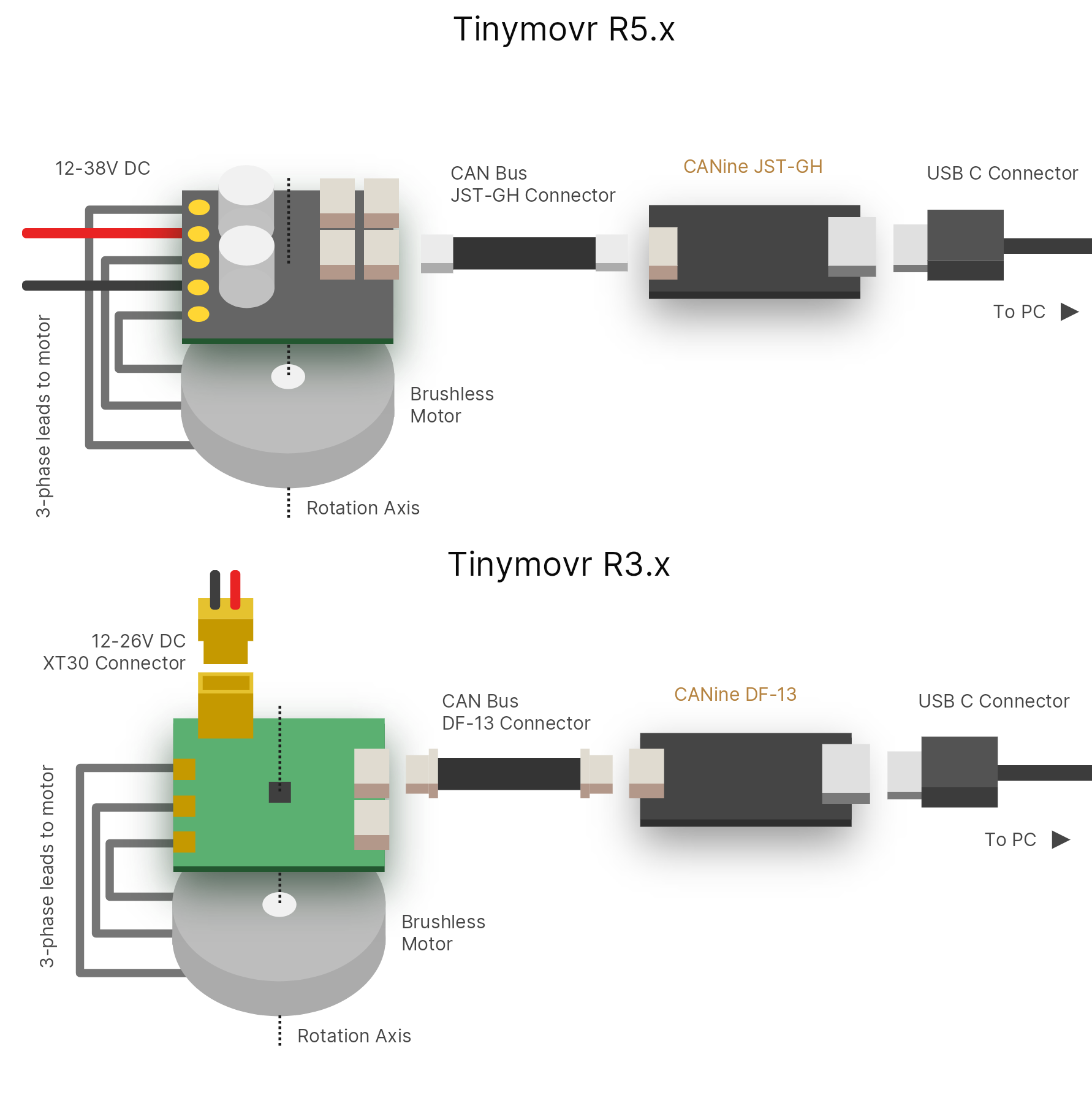
Electrical setup comprises three main parts: Motor connection, data connection and power connection. Below is a diagram with the electrical connection scheme.
Connecting Motor
Connect the three motor phases to the three terminals on Tinymovr. The order of connection is not important, motor direction will be determined during motor/encoder calibration.
The connection can be achieved in two ways. Either by soldering the motor leads directly on the terminals, or by securing the leads with a 2mm lug.
Note
If using a lug connection, ensure that the screw and nut are not rotating against the PCB surface, as this may remove parts of the soldermask or even conductive copper layer.
Connecting Data
Connect the CAN bus header to one of the two CAN sockets on the board. It is not important which one you choose. If this is a terminal node in the CAN network, you may need to use a termination resistor, as follows:
Tinymovr R3.x: flip ONLY the DIP switch labelled “CAN 120R” to on to enable the 120Ω termination resistor.
Tinymovr R5.x: you will need to provide an external 120Ω termination resistor.
In small setups with few nodes and short wires, it is better to enable just a single termination resistor, either on one Tinymovr board or on the CAN adapter. In setups with many nodes and long cables, you may need to enable termination resistors in both terminal nodes.
Warning
The UART pins in Tinymovr R5.1 have the silkscreen reversed. If you are planning to use UART with R5.1, consult Tinymovr R5 UART Silkscreen Reversed.
Connecting Power
Tinymovr R3.x can be powered from a 12-26V (3S-6S) power source.
Tinymovr R5.x can be powered from a 12-38V (3S-9S) power source.
With the power source off/disconnected, connect the power leads observing correct polarity. Turn on/connect the power source. Upon successful power-up, the onboard LED should light up.
Note
Each Tinymovr board has a capacitance of around 500μF/160. Such capacitance can introduce significant inrush current upon power-on, especially if several boards are connected to the same power supply. To prevent damage to components from overcurrent, the use of an inrush current limiter or a current-limited power supply is advised.